We have a new solution for you!
Installation
Transducer
a. It is recommended that a facility is cleaned prior to the installation of the USP to maximize its effect.
b. The Installation must be done while the stream is turned off. For safety, release the pressure and
remove any flammable gases and/or liquids within the facility.
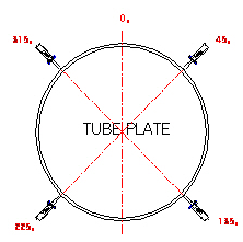
c. Place the Transducer around the facility at the specified positions shown in Fig. 1.
d. Clean the welding surface with a sandpaper or a grinder. Re-paint the welded part(s) after the
installation.
e. Position the Transducer squarely along the welding surface.
f. Only individuals who are certified for non-destructive welding (or equivalent) should perform the
welding. Welding may be done with Argon or Arc depending on the materials available at the facility.
g. The outside diameter of the weld bead must not exceed the wave-guide-rod diameter by more than
5mm. The weld bead must not contain any slag or gas bladder (Fig. 2).
Generator
a. Locate a suitable place for the USP Generator that provides an AC power supply to the Transducer
b. The location for the Generator must be within 30 meters from the Transducers.
(note: cable lengh for each Transducer: 30m at maximum)
c. Generators must be protected from sunlight, humidity, excessive heat or cold, and vibrations.
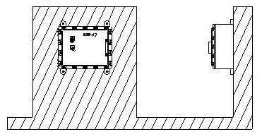
d. Generator should be installed vertically as shown in Fig. 3.
Generator and Transducer Wiring
a. Wire the power supply to the Generator per the diagram.
b. Wire the Generator to the Transducer per diagram.
c. Transducer cable specification: 600V FR-CVV-SB, 3* 1.25SQ from LS Cable Co. or equivalent type
Operation Test
An authorized representative of the Morko America must perform the final operating test to validate the
manufacturers warranty. This includes alignment and adjustment of the ultrasonic wave resonannce
frequency and power.
Transducer
a. It is recommended that a facility is cleaned prior to the installation of the USP to maximize its effect.
b. The Installation must be done while the stream is turned off. For safety, release the pressure and
remove any flammable gases and/or liquids within the facility.
c. Place the Transducer around the facility at the specified positions shown in Fig. 1.
d. Clean the welding surface with a sandpaper or a grinder. Re-paint the welded part(s) after the
installation.
e. Position the Transducer squarely along the welding surface.
f. Only individuals who are certified for non-destructive welding (or equivalent) should perform the
welding. Welding may be done with Argon or Arc depending on the materials available at the facility.
g. The outside diameter of the weld bead must not exceed the wave-guide-rod diameter by more than
5mm. The weld bead must not contain any slag or gas bladder (Fig. 2).
Generator
a. Locate a suitable place for the USP Generator that provides an AC power supply to the Transducer
b. The location for the Generator must be within 30 meters from the Transducers.
(note: cable lengh for each Transducer: 30m at maximum)
c. Generators must be protected from sunlight, humidity, excessive heat or cold, and vibrations.
d. Generator should be installed vertically as shown in Fig. 3.
Generator and Transducer Wiring
a. Wire the power supply to the Generator per the diagram.
b. Wire the Generator to the Transducer per diagram.
c. Transducer cable specification: 600V FR-CVV-SB, 3* 1.25SQ from LS Cable Co. or equivalent type
Operation Test
An authorized representative of the Morko America must perform the final operating test to validate the
manufacturers warranty. This includes alignment and adjustment of the ultrasonic wave resonannce
frequency and power.
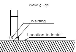

CAUTION!
Edge of welding must not be
more than 5 mm larger than
wave-guide-rod diameter.
Edge of welding must not be
more than 5 mm larger than
wave-guide-rod diameter.
Figure 2.
Figure 1.
Figure 3.